Repairing a Velotric Thunder 1 ST (2023) E-Bike
I recently got a Velotric Thunder 1 ST (2023) second-hand from an acquaintance. I was warned the electronics were on the fritz, but this seemed like an ideal project. I was hoping to find a Class 1 e-bike with a low top tube, flat bars, lots of sizing flexibility, and upright geometry, and this fit the bill.
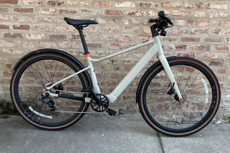
This bicycle had a number of firsts for me: e-bike, hydraulics, internal cable routing, integrated cockpit. The bike’s in a fully working state now thanks to some replacement parts, a lot of help from Velotric support, and a few hours of my time spent.
I enjoy riding this bike and that the e-bike aspects of it are very subtle. It’s relatively light and fast even without any pedal assist. This was my first e-bike and I absolutely understand why folks enjoy these. Despite the work I had to do I’m really glad I have this bike. It’s great for a hot day when I don’t want to sweat as much or if I’m not feeling as strong as I could and need a boost while riding around town.
Warning! I am not a professional bicycle mechanic! I assume no responsibility for anything in this article or related works. This article is not authoritative in any way. You should have a professional bike mechanic perform any repairs or maintenance or similar work on your bike.
Battery Issues
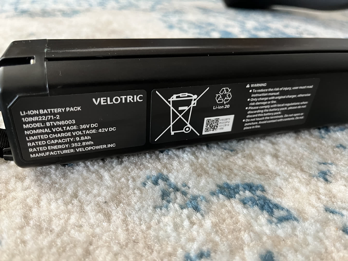
The first and primary issue I encountered with this bike was regarding the battery. I found inconsistencies and issues when it came to charging and discharging the battery. The battery would seem to charge suspiciously fast, but then drain just as quickly. I was unable to reliably explain the behavior. At times it seemed like it would take a day to go from 1 charging dot indicator to 4 changing dot indicators. At other times it would seem to charge normally.
To try and eliminate possible external factors I removed all the electronics from the Velotric. Note, tie a string, wire, cable, etc., around the end of the battery cable where it meets the top tube module. It can be challenging to fish that cable through later.
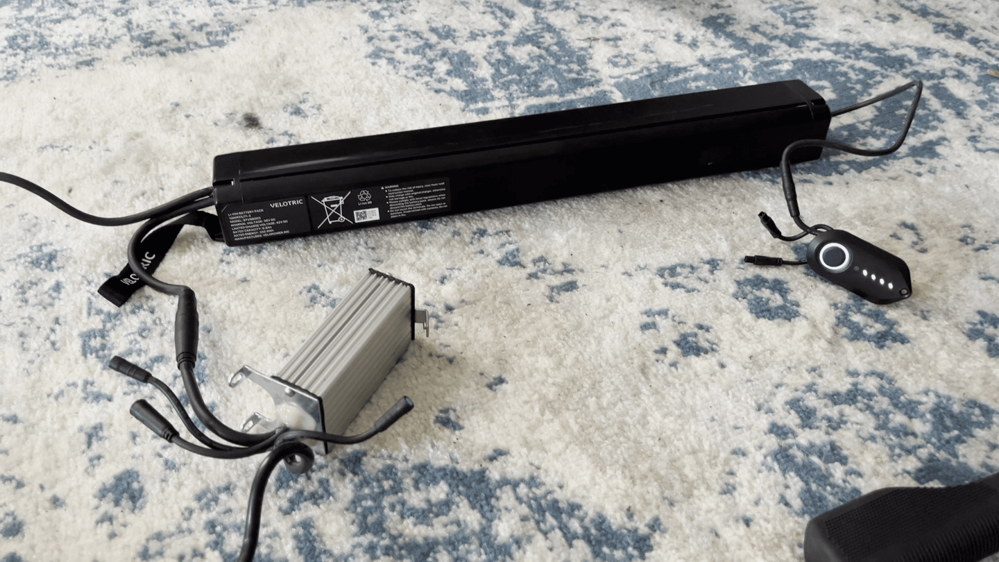
With the electronics removed I tried various combinations of connected components to see if anything made a different while charging. I tried to keep the components undisturbed while charging in case a loose wire might be at fault. I let each experiment run for a minimum of an hour and I ran all these experiments one after the other on the same day.
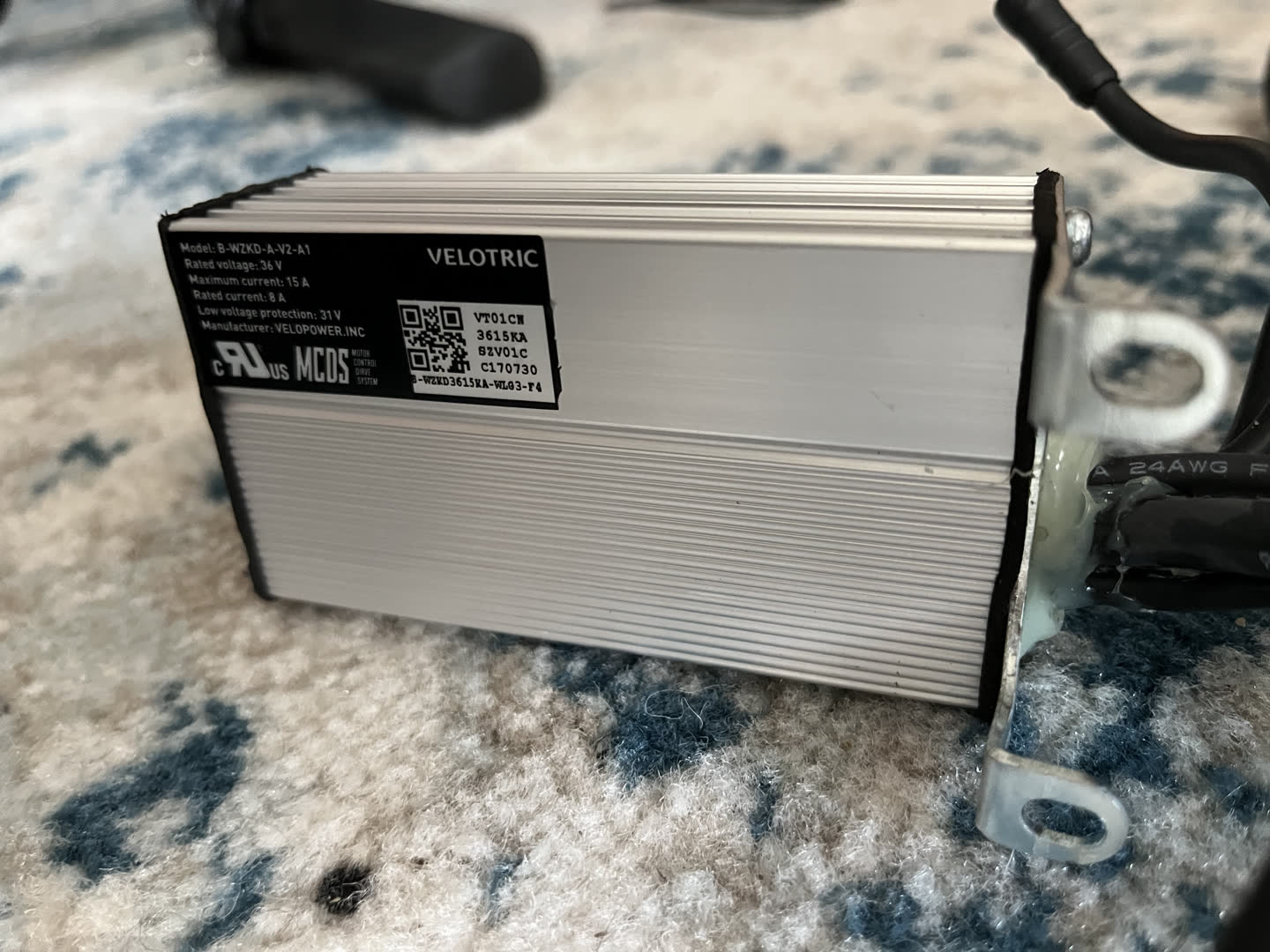
Experiment 1: Motor controller, top tube module, battery, and charger
After one hour a single charge light was flashing.
The AC/DC charger light was green. The charger was cold. It seemed like the battery was not charging. I unplugged the charger and the top tube module powered off almost immediately.
If I turned the top tube module on again it would flash rapidly with one battery indicator light and turn itself off after several seconds.
Experiment 2: Top tube module, battery, and charger connected
It seemed like the battery would not attempt to charge at all without the motor controller connected. I let it charge for an hour. The top tube module did not show any indication that the battery was attempting to charge. Eventually I removed the charger and it seemed like the battery had no charge in it. It powered off almost immediately.
If I turned the top tube module on again it would flash rapidly with one light and turn itself off after several seconds.
Experiment 3: Motor controller, top tube module, battery, charger, and handlebar remote control connected
I let this test run longer than an hour. It ran for several hours total.
After several hours, abruptly, the top tube module charge indicator lights went from a single flashing charge light to all four solid lights implying it was fully charged. I unplugged the charger and it seemed like the battery had never charged. The top tube module powered off almost immediately once the charger was disconnected.
If I turned the top tube module on again it would flash rapidly with one light and turn itself off after several seconds.
Experiment 4: Motor controller, battery, and charger connected
Without a top tube module there wasn’t a progress indicator for charging status. I charged the battery for two hours.
I unplugged the charger, connected the top tube module, and it seemed like the battery had never charged. The top tube module powered off almost immediately.
If I turned the top tube module on again it would flash rapidly with one light and turn itself off after several seconds.
In all of those experiments the light on the AC/DC charger was green and never red. It never warmed up and never seemed to be charging the battery. At this point I was nervous that the battery, a very expensive piece of equipment, might be damaged.
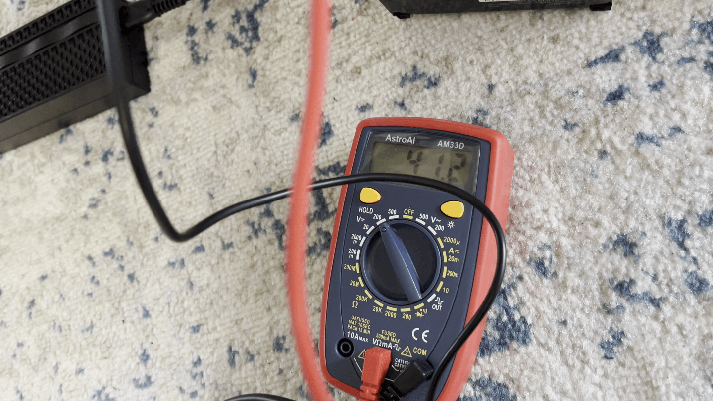
Using a multimeter I measured ~42V being output from the charger. As far as I could tell the charger was working properly.
I failed to record the voltage at the battery, but I remember it was low and seemed to agree with the experiments in that it was not charged.
One day, after leaving the battery and charger connected for 24 hours, it suddenly seemed to have charged. I don’t know what changed or why it would suddenly receive a charge, but the battery had life. I measured somewhere ~40V at the battery positive and negative terminals.
The battery seemed to have a charge this time, and worked as expected, but the unreliable behavior made me nervous something must not be working right. I went on a test ride to try and drain the battery from full and observe any relevant behavior.
On my test ride the Velotric power status lights dimmed with less and less time between each level as the ride went on. I did use turbo (purple/pink) mode for much of the ride, but the battery range still seemed poor to me. For one, the overall mileage was very low. Additionally, the inconsistent time between each status light seemed to imply an issue with the health of the battery.
- 4 lights for the first ~3.5 miles (~15 minutes)
- 3 lights for an additional ~2 miles (~10 minutes)
- 2 lights for ~1.2 miles (~6 minutes)
- 1 light for ~0.6 miles (~3 minutes)
I don’t expect the battery to last very long on purple/turbo mode, but I do find it odd how misleading the battery status lights were. It seems that others may have posted about a similar issue.
I weigh ~150lb. I expected 1) more consistent battery behavior between each status light and 2) longer battery life overall, even on turbo mode. Based on a review of this same bike that went a similar distance to my ride, but also with much more elevation than I encountered (my ride was almost completely flat) it seems like the battery should have lasted longer for me especially since this other person was on turbo mode “quite a bit” and on steep hills as they point out. In another review some testers got about 25 miles in turbo mode, which is roughly 3x as much range as I had on my test ride.
Based on previous inconsistent behavior when charging the battery I decided to try and record it charging from completely dead to fully charged if I could.
I started charging at 9 PM local time.
- 1 light by 9:09 PM (25% charged in 9 minutes)
- 2 lights after an unknown amount of time (50% charged in less than half an hour)
- 3 lights by 9:27 PM (75% charged in less than half an hour)
- 4 lights by ~11 PM (100% charged in about two hours)
The battery from “dead” to fully charged in ~2 hours and seemed to charge as inconsistently as it discharged. From what I’ve read a typical charge time is 6 hours, which made me think something was wrong with my bike and I may need a replacement part.
I wasn’t sure what to do at this point. I didn’t trust
that I had narrowed the issue down to the motor controller,
battery, or the top tube module. I opened a Velotric support case
to seek help. They recommended I might need a top tube module,
which sounded fine to me since that was much more affordable than
a new battery. I was able to buy a new replacement computer/top
module for $50. In the invoice it’s listed as
ST020701C top tube module × 1.
This new module worked perfectly. The battery charged properly, status lights on both the charger and the top tube module seemed to reflect reality, and the battery has had longer and more reliable range.
Front Light Not Working
The headlight on this bike would not turn on, and I wasn’t initially sure if I cared to replace it. I knew the remote control was OK because that was working to change e-assist modes and change settings without issue. I thought it could be a problem with the computer or the light itself.
After replacing the computer I felt confident the light must have an issue.
I eventually cut and stripped the wires from the top tube module to the light so I could perform some tests. I added a resistor and an LED both in parallel and in series with the headlight. I could get the LED to turn on. I was also able to measure voltage between the two headlight wires. It seemed like electricity was flowing fine through the light, but it was not powering on.
I considered opening up the light, but it seemed pretty well sealed and I was afraid any attempt to open it might break it further.
I was able to buy a replacement light from Velotric for $50. The
invoice listed this part as
ST010706A - Front Light × 1 and this worked
perfectly. The mounting hardware was almost identical to the old
light and it behaves exactly as expected.
Frayed Cables
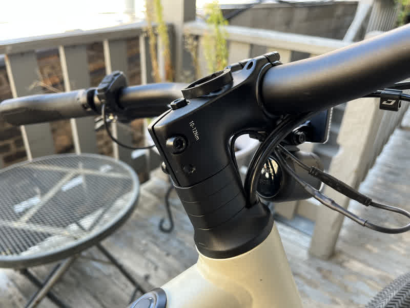
The headlight, remote control, and torque sensor cables were all frayed to varying degrees. I think the cable-routing on the bike is one thing that could really be improved. From what I can tell, newer models have computers that aren’t integrated in the frame and other changes that probably make this less of an issue. On this model the electronic cable housing is fairly soft and easily torn from pressure.
I failed to take a photo, but the integrated cable routing was not something I was used to and I found it a pain to deal with even though it looks nice.
The headset for this bike has front and rear hydraulic hoses running through it as well as the cable from the battery to the computer and the cables from the computer to the headlight and from the computer to the remote control on the handlebars.
It’s a tight squeeze for all the cables in the headset and I saw damaged cable housing where it seems like friction and tension in the headset strained things. I appreciate that newer model Velotrics seem to have non-frame-integrated computers which simplifies the cable routing a bit.
Torque Sensor Wires
While working on the charging issue for this bike I opened up the bottom access panel and noticed frayed wires. I eventually realized these were for the PAS torque sensor. The wires on the torque sensor were fairly badly damaged.
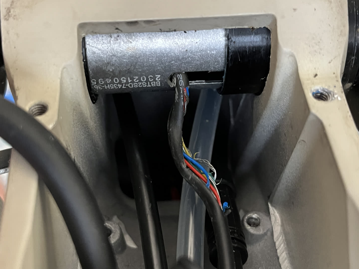
I was hoping to find a generic replacement torque sensor online, but had no luck in that search. I found nothing matching the model number of my bottom bracket. I found bottom brackets of the same length and voltage, but with fewer than 36 PAS sensor points.
Model: BBTS2SD
Length: 73mm
PAS Sensor: 36 Pulse
Power Standard: DC 5V
Manufacturer: VELOPOWER, INC
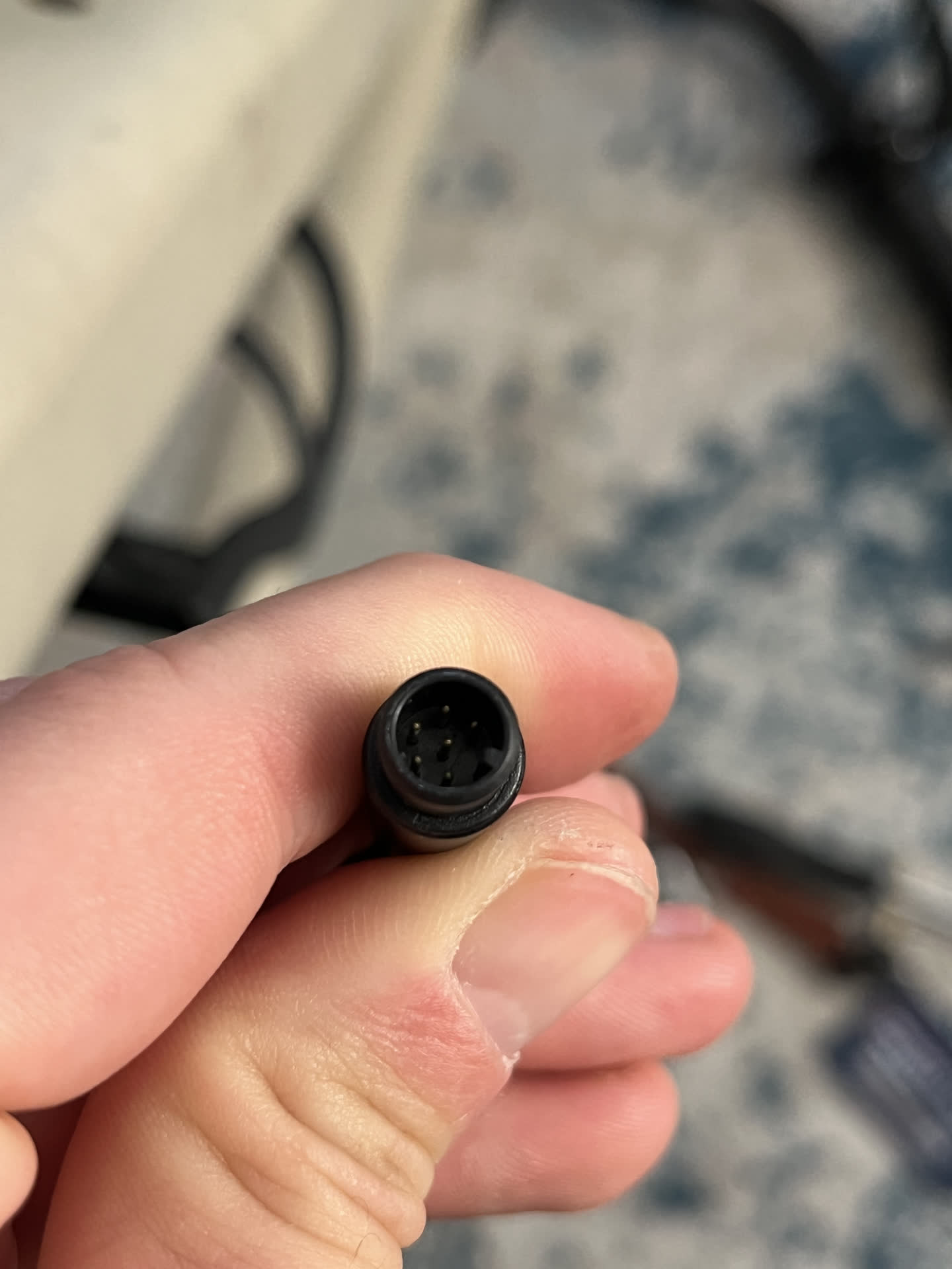
Among possible generic replacements I was also unable to find a suitable bottom bracket that seemed to have the same plug.
I decided to buy a replacement torque sensor bottom bracket from Velotric as well as try to repair the damaged torque sensor in the meantime.
The replacement torque sensor was more expensive than I’d
hoped, but was similar in price to fairly generic and popular
bottom bracket torque sensors I found online. I opened a support
claim with Velotric and they were able to send me a new part. It
was $129 and listed as
ST020703A- Torque Sensor × 1 on the invoice. While I
waited for the replacement to arrive in the mail I set to work on
repairing the wires for the damaged device.
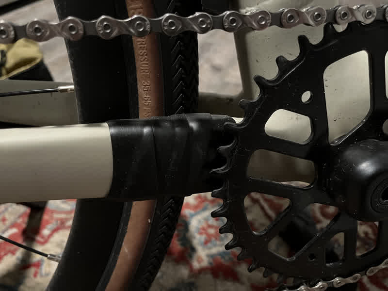
This bikes uses a standard square-taper spindle cartridge-style bottom bracket. The frame has a threaded shell. Something new to me is that the bottom bracket has a slot milled/cut out from the center towards the drive-side of the bottom bracket. This is so the torque sensor wires can exit the bottom bracket.
As can be seen in this video, if the bottom bracket is engaged in the drive-side cup while the cup is tightened or loosened, then the wires meet an edge of the bike frame that digs into them. I assume the wires may have been originally damaged by the bottom bracket rotating and rubbing the wires against the frame here.
I learned that I had to be careful while tinkering and make sure the bottom bracket was not at all engaged with the drive-side cup while making adjustments. I fully removed the non-drive-side cup first, slid the bottom bracket out and away from the drive-side cup so it had no contact, and then removed the drive-side cup.
I decided to remove the bottom bracket to get better leverage for soldering repairs. Aside from the integrated torque sensor and its wires this is a typical JIS square-taper bottom bracket.
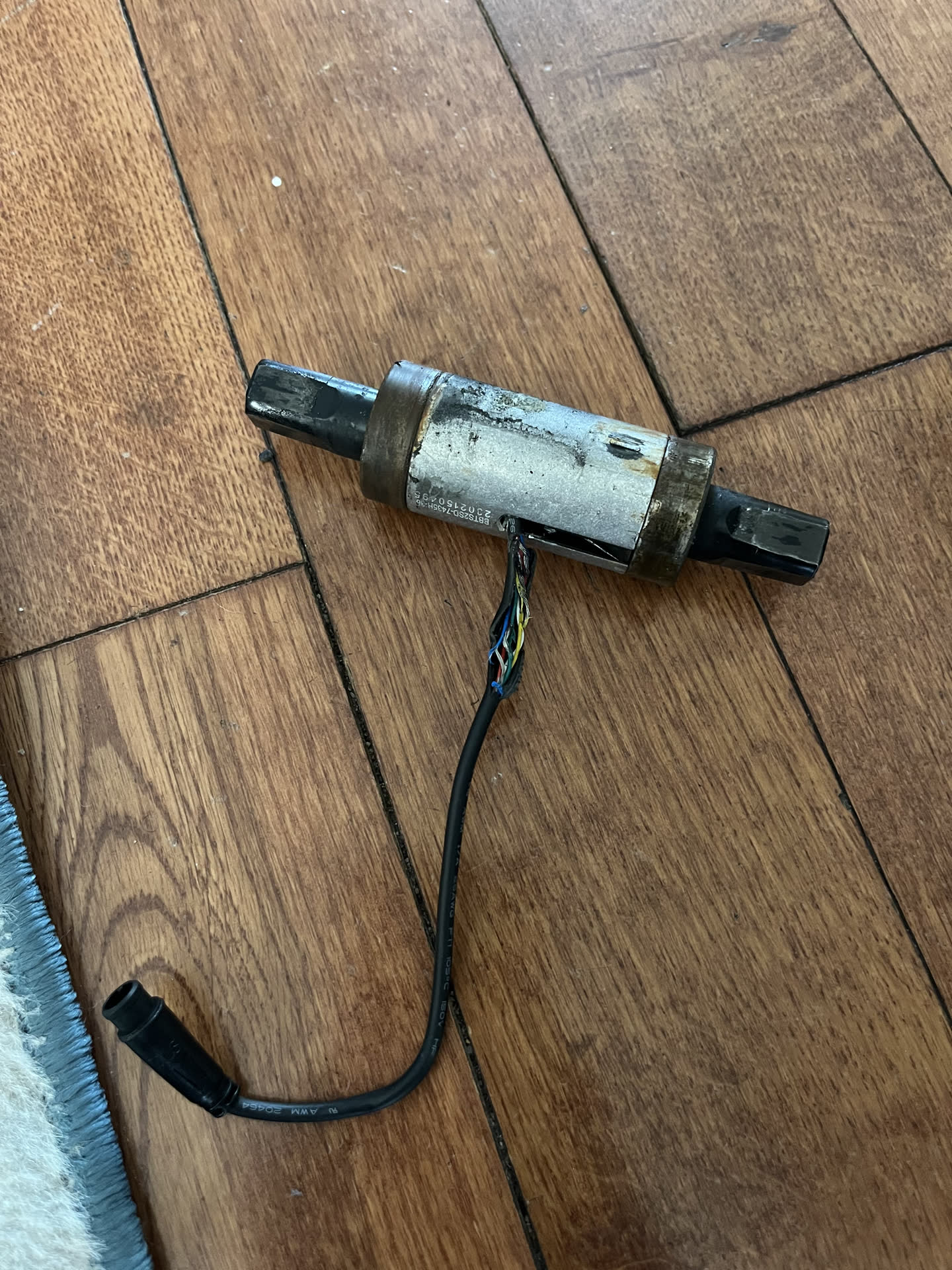
I was nervous that the torque sensor wires would be very difficult to repair (for me at least) because the wires were frayed very close to the body of the bottom bracket cartridge. I am not well-practiced in soldering and electronics. I can handle the basics, but this was a technical challenge for me.
I spread apart the wires to get a better grasp on which wires were damaged, where they were damaged, and how badly they were damaged. No wires were totally severed, or even frayed all that badly. They were exposed, and probably making contact in the bike, which is bad, but overall they were in decent shape.
I decided not to cut and solder the wires and instead cut some heat shrink tubing, wrapped it around the wires, then glued them sealed again. I figured this would be the least intrusive way to protect the wires and make sure they’re not touching one another or other bare metal inside the bike.
I used my heat gun to secure the heat shrink tubes. Here’s where I made a terrible mistake. I went overboard with the heat shrink wrap. I put another thicker layer of tubing around the wires.
Unfortunately, I failed to consider re-installing the bottom bracket into the bike. I don’t typically have to worry about wires when installing a BB, and didn’t think about the fact that I have to install this back in the bike and squeeze the wires through too.
The wire housing was simply too thick, and I had to cut away at the heat shrink tubing to get back down to bare wires. In the process, I cut through a wire by mistake. Now I had to undo all that work and solder the wires anyway. Whoops.
Cutting the wires was what I feared from the start. If I made a mistake I might get so close to the bottom bracket that I couldn’t safely solder anything (with my skill set) and would lose any good solder points on the wires. In removing the heat shrink tubing from my failed previous attempt some wires were cut very close to the bottom bracket. Thankfully, I was able to solder in some extra wire, carefully heat shrink wrap them without having to cut and glue them together, and overall I think this went better than expected.
My soldering skills aren’t great, and I didn’t have matching wire for everything beyond red, white, and black, but the connections seemed decent. This time I inserted the bottom bracket back into the bike before adding any excessive tubing. I had to make sure the wires were thin enough that I could squeeze them through the holes in the frame with the bracket without destroying the wires.
I decided not to add any more heat shrink tubing to the bundle of wires. The only wrap I had to surround the bundle would’ve been thick, and cable management inside this access panel is really tight. I was worried that arranging these torque sensor wires might damage them so I wanted them as compact as possible.
To my shock, this actually worked! The pedal assist torque sensor seems to work fine. I hate how tightly all the wires are packed into the bike, but it works! If anything fails again I can delicately install the replacement bottom bracket instead.
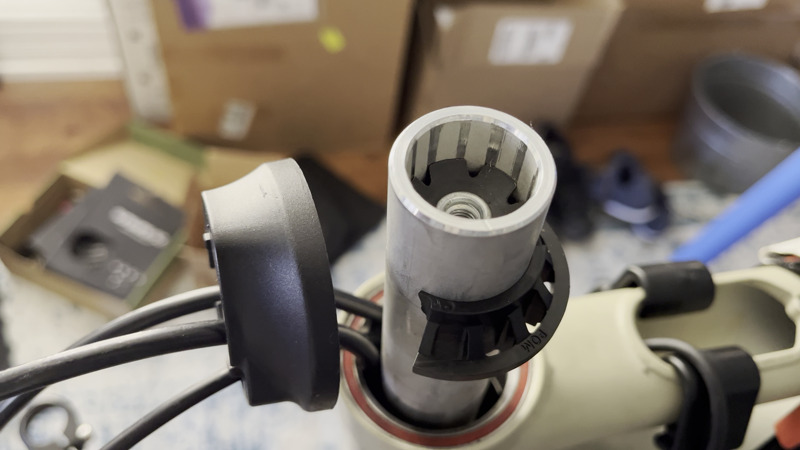
Compression Ring/Cable Guide
There may be a better term for this component, but since it contacts the upper-bearings in the headset while holding the steering tube center and guiding the cables I think it’s fair to say it’s a compression ring and cable guide.
This component is made out of some sort of plastic and the tabs for guiding some internal routing cables through the headset assembly broke during maintenance.
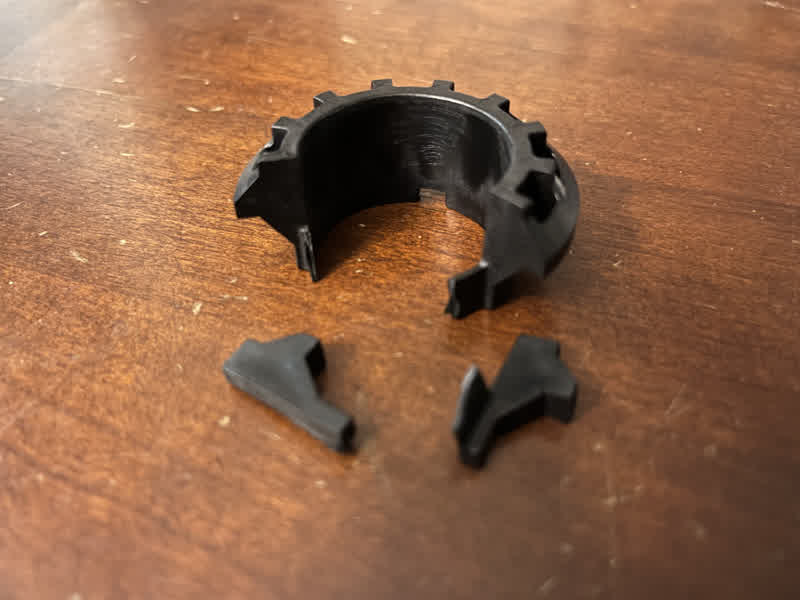
Based on how the computer module was installed in the top tube I was obligated to use something with internal cable routing. This broken component (even before it was broken) was not a complete circle. It was open-ended, which means it could easily be taken on and off the bike without having to re-run any cables or hoses.
The dust-cap that sits on top of this ring is not slotted. It is a solid circle. To replace it would mean re-running cables and hoses.
Unfortunately, Velotric customer support informed me that they do not sell a replacement compression ring. The part had a number stamped into it, but I found no information about it in various searches. I could have maybe purchased an entirely new cockpit/upper-headset assembly like the Shimano Pro Internal Routing Headset, but the cost and effort involved in having to re-run my hydraulic brake hoses through an entirely new set of components was more than I wanted to take on.
I purchased several third-party compression rings that were slotted/notched/split/open in the hopes I could find a suitable replacement. Nothing I found adequately made contact with the headset dust cover to provide appropriate pre-load compression on the bearings.
In the end, I decided that although a couple tabs had broken off this component, it was still the safest option, and kept with it. I might try to 3D print a replacement in the future, but more likely when the hydraulics need maintenance I’ll swap out the headset with something more robust.
Cosmetic Frame Scratch
I wasn’t too concerned about this scar on the chainstay, but wanted to cover it up. I believe either chain-suck or perhaps a mis-sized or mis-aligned chainring caused the gouge. No worries on my end as the damage wasn’t deep at all. It only went slightly beyond the paint.
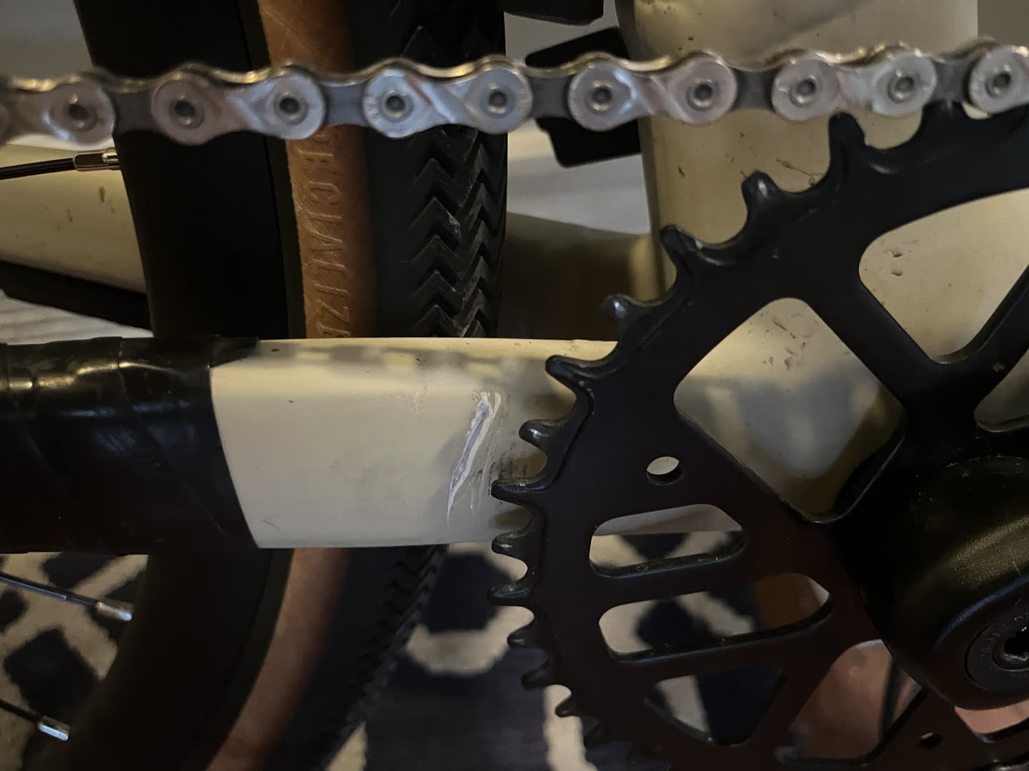
I cleaned the affected area, let it dry, and (poorly) applied some 3M Scotch® Rubber Mastic Tape 2228 to cover this and prevent any potential further damage.
Notes
- https://www.youtube.com/watch?v=erSF6TkLhOk
- https://www.youtube.com/watch?v=QWPDtg0fIgA
- https://www.reddit.com/r/ebikes/comments/17y20gn/an_honest_review_of_the_velotric_thunder1_st_a/
- https://www.reddit.com/r/ebikes/comments/14p2vio/my_velotric_thunder_1_st/
- https://www.youtube.com/watch?v=brNO_GXxsDY
- https://www.youtube.com/watch?v=ckbZINqV4ho
- https://www.youtube.com/watch?v=smiVlCjc64k